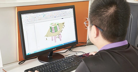
Rapid die casting with special tools is a method used by foundries for decades of die-casting prototypes. The advent of stereolithography and computer-aided design modeling has made people interested in the applications provided by this software.
You can use secondary machining to add more geometries. The advantage of this method is that it can provide die-cast parts in a short period of time because the parts have ideal heat transfer and the same physical properties as the end parts when processed as castings. Since the parts operate in the die-casting machine, a large number of parts can be produced in a short time span, thereby increasing considerable economies of scale.
The die-casting machine can accommodate the parting line and has a side die for manually loading the materials used in the rapid prototyping method. It is not recommended to use this side-pulling method with fine details or embedded waterlines. Usually, the lead time of the rapid casting process is 5 to 8 weeks, which also depends on the complexity and size of the required end parts.
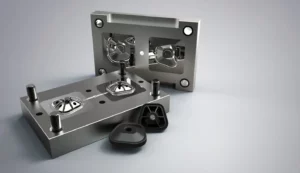
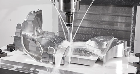
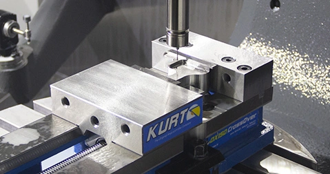
The initial geometric pattern was created by CNC or SLA, and the shrinking aspect was scaled down. For this purpose, a parting line was developed, and a soft negative hardness tester was created in the shape of a tool. If necessary, the details of the cavity can be supplemented by CNC machining or electrical discharge machining.
Trim the insert, and then install it into the mold base, where an additional thimble is placed. Process the overflow and gate, and set the die casting mold to run in the standard die casting machine. Although surface finishing requires trimming and secondary machining as needed, parts can be run in almost any die-cast alloy.


